fbpx
SLS, Nylon 6 Mineral Filled

Ultrasint® PA6 MF

Selective Laser Sintering [SLS]

Material info

About Ultrasint® PA6 MF

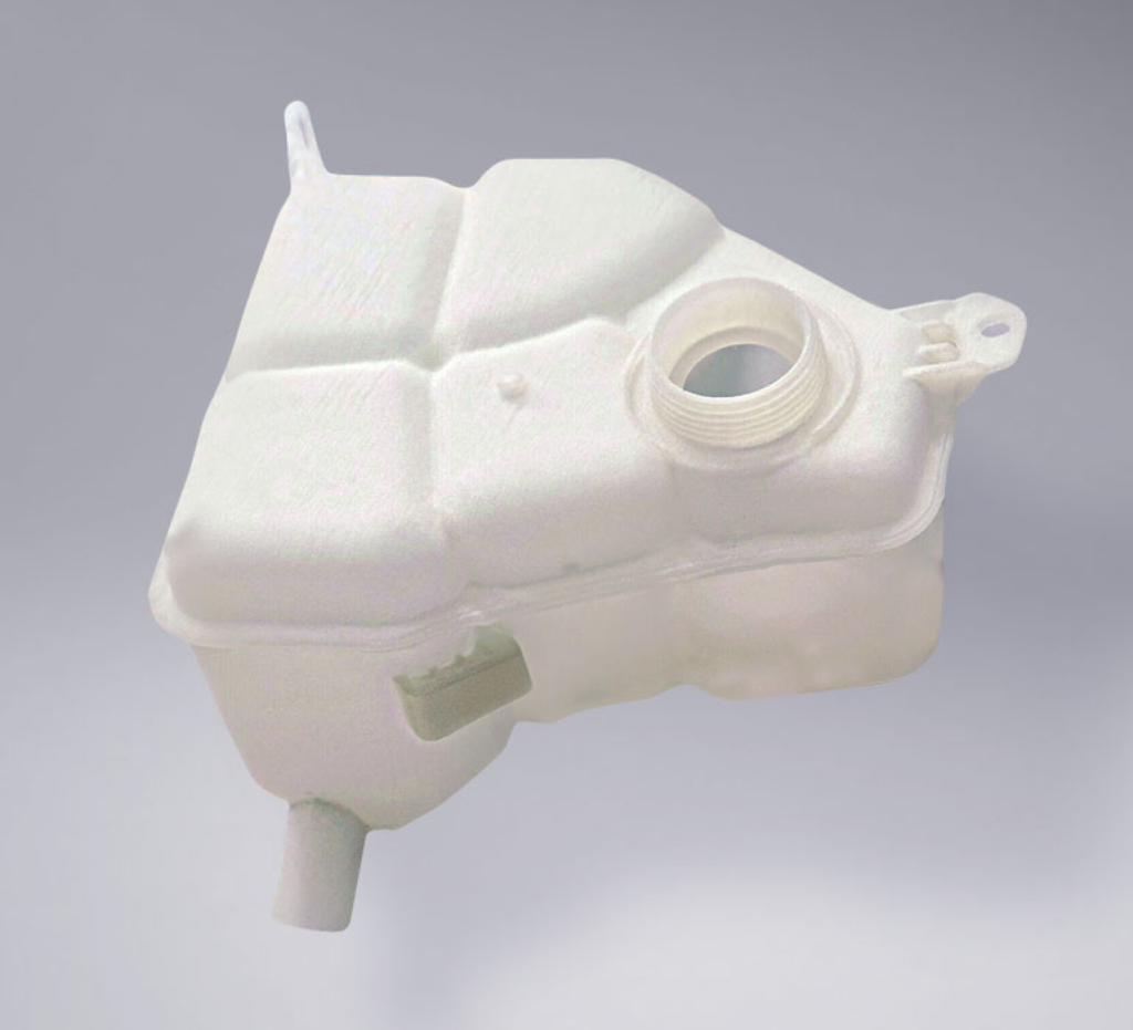
Ultrasint® PA6 MF is an excellent choice for applications where high stiffness, strength and heat stability are key requirements. The ‘mineral-filled’ reinforcement embedded in the polymer particles of Ultrasint® PA6 MF lead to isotropic properties similar to those of injection molded parts. Parts printed with Ultrasint® PA6 MF also feature superior stiffness, enhanced impact strength and excellent heat stability. Typical applications include automotive components in the engine compartment, structural parts and functional prototypes. Parts printed from Ultrasint® PA6 MF are naturally black.

Color & Finishes

Black

Technology

  • Selective Laser Sintering [SLS]

Material Properties

Tensile Strength X:
62 MPa
Tensile Strength Z:
40 MPa
Heat Deflection:
209ºC
Tensile Modulus X:
3300 MPa
Tensile Modulus Z:
3100 MPa
Elongtation at Break X:
7.0%
Elongtation at Break Z:
1.6%

Description

Applications
Engine bay parts, Media flow and storage parts (i.e. oil), Housings and covers, Tooling equipment & molds, Multi-purpose industrial goods
Properties
High strength & rigidity, Very high HDTs, High isotropic rigidity

Design Guidelines

Bounding Box

Bounding Box Max
375 x 375 x 440 (mm)

Bounding Box Min
X + Y + Z > 10 (mm)

The bounding box is a 3D imaginary outline of a box that encloses the smallest area occupied by your model. Your model must be within the minimum and maximum bounding box sizes. If the size of the model is close to the maximum bounding box, then the printing orientation will be restricted.

Walls

Supported Wall Thickness Min
1.5 (mm)
Unsupported Wall Thickness Min
1.5 (mm)
A supported wall is connected at least on two sides of the wall, while an unsupported wall is connected only on one side of the wall. Walls that do not meet the minimum requirements may not survive printing and cleaning processes. Additionally, models may still be rejected based on the wall geometry of the model. Please consider the size of your model and reinforce the walls or add support structures as needed as minimum guidelines will not always be adequate for large models.

Wires

Supported Wires Min
1.5 (mm)
Unsupported Wires Min
1.5 (mm)
A wire is a circular, rectangular or even triangular feature that is thinner in its unconnected directions than its length. A supported wire is connected at least on two sides of the model, while an unsupported wire is connected on one side of the model. Wires that do not meet the minimum requirements may not survive printing and cleaning processes. Additionally, models may still be rejected based on the wire geometry of the model. Please consider the size of your model and reinforce the wires or add support structures as needed as minimum guidelines will not always be adequate for large models.

Details

Details Min Embossed
0.5 wide, 0.5 high (mm)
Details Min Engraved
0.5 wide, 0.5 deep (mm)
For text, the ratio between width and depth, should be 1:1 and sans-serif fonts are preferred for line weight consistency.

Escape Holes

Single Escape Hole Diameter (Min)
8.0 (mm)
Multiple Escape Hole Diameter (Min)
5.0 (mm)
Escape holes are necessary to empty the support material of a hollow model. Two escape holes at the opposite ends of the model is optimal for the support removal process. Please consider the size of your model and make the escape holes bigger or add more escape holes as needed as minimum guidelines will not always be adequate for large models.
A single escape hole at the end of a cavity will not allow material in the corners near the escape hole to fully escape. So we recommend multiple escape holes at both ends of the cavity.

Clearance

Min
0.5 (mm)
Clearance is the space between two individual parts in a model. If the space among the individual parts do not meet the minimum clearance, then parts can fuse together or can be difficult to clean. This is important for movable pieces like hinges, gears, etc.

Sprues

2.0 (mm)
Sprues are wires that keep two or more parts together. Parts should be connected with a minimum of two sprues each. Please consider the size of your sprues and increase them as needed as minimum guidelines will not always be adequate for large models. If the sprues are within the guidelines and are broken, but there is no damage to your model, we will still ship them as is.

Interlocking & Enclosed Parts

Interlocking
Yes

Enclosed
Yes

Parts in File

Max
100 parts in file

Accuracy

Accuracy ± 0.3% (minimum of ± 0.3 mm)
For example: a product with dimensions of 50x50x100 mm can be 0.15 mm + 0.0015*100 mm = 0.3 mm bigger or smaller in any direction.

Other Materials

SLS, Polypropylene (PP)
Ultrasint® PP nat 01
Chemical resistanceHigh ductilityHigh elongation at break 30%
Application: Coolant reservoirs, custom production tools, electrical and sports goods, health care and orthopedic products
Photopolymer
Full Color Mimaki
Application: Figurine, medical models, architecture, terrain models, realistic visual prototypes
otto-logo-black
© 2024 ® = Registered trademark of BASF 3D Printing Solutions GmbH  Privacy policy Terms and conditions

We use cookies to offer you a better browsing experience, including personalized advertising. By continuing to use the site you agree to their use.

Learn more