fbpx
Also known as HP Multi Jet Fusion PA12, Professional Plastic, HP Nylon Plastic, PA12, Polyamide

MJF Plastic PA12

HP Multi Jet Fusion [MJF]

Material info

About MJF Plastic PA12

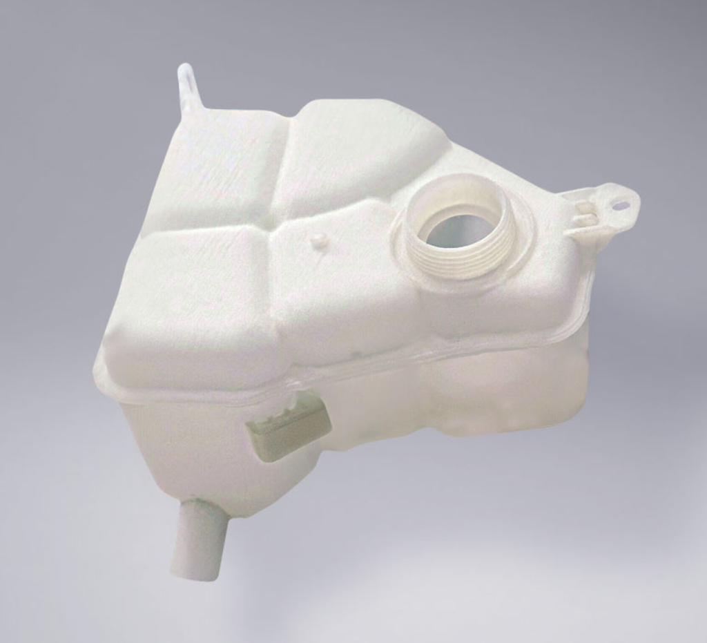
Multi Jet Fusion (MJF) Plastic PA12 is HP’s nylon plastic with excellent mechanical properties and a slightly grainy finish. In black, it is also available in a smooth and slighlty glossy finish. MJF Plastic PA12 is an ideal choice for a wide range of applications from industrial parts to durable end-use goods. Its strength, durability and stiffness make it great for functional parts, such RC car parts and mounts. It is also popular for home decor, eyewear and games. MJF Plastic PA12 is printed using HP’s Multi Jet Fusion technology and supports very complex geometries and thin features.

Technology

  • HP Multi Jet Fusion [MJF]

Material Properties

Material Properties
high strength & durability, good impact resistance professional finish, thin features & interlocking parts

Description

Applications
Mechanical & structural parts, mounts, cases, eye frames, tech accessories, drone parts, home decor, miniatures, art, prosthetics

Design Guidelines

Bounding Box

Bounding Box Max
284 x 380 x 380 mm (Gray Natural and Black Smooth) 210 x 210 x 360 mm (Black Natural)

Bounding Box Min
X + Y + Z > 9 mm (Natural) 10 x 10 x 10 mm (Smooth)

The bounding box is a 3D imaginary outline of a box that encloses the smallest area occupied by your model. Your model must be within the minimum and maximum bounding box sizes. If the size of the model is close to the maximum bounding box, then the printing orientation will be restricted.

Walls

Supported Wall Thickness Min
0.4 mm (Natural) 1.5 mm (Smooth)
Unsupported Wall Thickness Min
0.5 mm (Natural) 1.5 mm (Smooth)
A supported wall is connected at least on two sides of the wall, while an unsupported wall is connected only on one side of the wall. Walls that do not meet the minimum requirements may not survive printing and cleaning processes. Additionally, models may still be rejected based on the wall geometry of the model. Please consider the size of your model and reinforce the walls or add support structures as needed as minimum guidelines will not always be adequate for large models.

Wires

Supported Wires Min
0.8 mm (Natural) 1.5 mm (Smooth)
Unsupported Wires Min
0.9 mm (Natural) 1.5 mm (Smooth)
A wire is a circular, rectangular or even triangular feature that is thinner in its unconnected directions than its length. A supported wire is connected at least on two sides of the model, while an unsupported wire is connected on one side of the model. Wires that do not meet the minimum requirements may not survive printing and cleaning processes. Additionally, models may still be rejected based on the wire geometry of the model. Please consider the size of your model and reinforce the wires or add support structures as needed as minimum guidelines will not always be adequate for large models.

Details

Details Min Embossed
Natural: 0.2 mm high & wide (0.4 mm high & wide for readable text, logos, and icons) Smooth: 0.5 mm wide, 0.3 mm high
Details Min Engraved
Natural: 0.2 mm high & wide (0.4 mm high & wide for readable text, logos, and icons) Smooth: 0.4 mm wide, 0.3 mm deep
For text, the ratio between width and depth, should be 1:1 and sans-serif fonts are preferred for line weight consistency.

Escape Holes

Single Escape Hole Diameter (Min)
4.0 mm (Natural) 10 mm (Smooth)
Multiple Escape Hole Diameter (Min)
2.0 mm (Natural) 8.0 mm (Smooth)
Escape holes are necessary to empty the support material of a hollow model. Two escape holes at the opposite ends of the model is optimal for the support removal process. Please consider the size of your model and make the escape holes bigger or add more escape holes as needed as minimum guidelines will not always be adequate for large models.
A single escape hole at the end of a cavity will not allow material in the corners near the escape hole to fully escape. So we recommend multiple escape holes at both ends of the cavity.

Clearance

Min
0.6 mm (Natural) 5.0 mm (Smooth)
Clearance is the space between two individual parts in a model. If the space among the individual parts do not meet the minimum clearance, then parts can fuse together or can be difficult to clean. This is important for movable pieces like hinges, gears, etc.

Sprues

2 mm thick, attached in at least 2 places per part
Sprues are wires that keep two or more parts together. Parts should be connected with a minimum of two sprues each. Please consider the size of your sprues and increase them as needed as minimum guidelines will not always be adequate for large models. If the sprues are within the guidelines and are broken, but there is no damage to your model, we will still ship them as is.

Interlocking & Enclosed Parts

Interlocking
Yes

Enclosed
Yes

Parts in File

Max
Natural: Up to 250. Smooth: Up to 10.

Accuracy

Accuracy Natural:±0.25 mm + 0.1% of the length Smooth: ±0.4% (with a lower limit of ±0.2 mm)
For example: a product with dimensions of 50x50x100 mm can be 0.15 mm + 0.0015*100 mm = 0.3 mm bigger or smaller in any direction.

Other Materials

SLS, Polypropylene (PP)
Ultrasint® PP nat 01
Chemical resistanceHigh ductilityHigh elongation at break 30%
Application: Coolant reservoirs, custom production tools, electrical and sports goods, health care and orthopedic products
Photopolymer
Full Color Mimaki
Application: Figurine, medical models, architecture, terrain models, realistic visual prototypes

We use cookies to offer you a better browsing experience, including personalized advertising. By continuing to use the site you agree to their use.

Learn more